Buttons – Description
♦ Back ♦ History ♦ Description ♦ Schematics ♦ Performance ♦ Pictures ♦
A redesign of this beast had always been in the back of my mind as I was going through school. I did come upon an ideal chassis for it: a 1U 19″ rack mount chassis. It would be the perfect fit and was the motivation I needed to get going again. So, after 4 years or so out of college, I started gathering parts for round two of this project. This design is what I came up with. One of the key features of the design is modularity. I knew myself well enough to know that I would need to be able to swap out any part of the unit without having to redesign/rebuild the others.
Preamplifier
Design
Since the rekindling of this project happened to coincide with my delve into the world of electron tube audio, I decided to build a line stage preamplifier into the chassis. I still had that cache of 12AU7 tubes from my old Thomas organ, so that became the tube that I designed the preamp around. It turned out to be the right tube for the job anyway.
This is where the project started getting a little out of control. I had just acquired a Technics SH-AC500D DTS/Dolby Digital Decoder for my future home entertainment system off of eBay. I wanted the ability to control the volume of the front and rear speakers from one location, which meant I would need a 4-channel preamplifier. In order to take advantage of my equalizer and digital audio processor, the routing would have to be: source->selector->equalizer->processor->decoder->preamps->amps. Since the selector and preamps would be in the same unit, I could bypass all the other junk at the push of a button for a “purist mode”. I don’t know why, but I decided to stick with this topology and designed the preamp based on that. With a nice pile of 12AU7s and a big Hammond 1U rack-mount chassis (17x13x1.75 inches), why not make the drivers to the equalizer with tubes as well?
After exploring a number of topologies, I decided on the “mu-follower” for the preamp stage. Two 12AU7 halves in a mu-follower configuration yields a gain of about 17.5, which is more than enough. The main thing that attracted me to this topology was the relatively low output impedance. The driver section of the preamp, which would drive the equalizer, was an obvious choice: the cathode follower with an active load using 12AU7s. All of this would require a total of six tubes, one per channel.
Construction
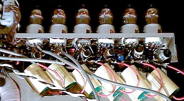
The preamp/driver section of the unit is mounted on its own assembly and can be easily swapped out with something else.  Unlike the rest of the components, the preamp is all point-to-point and stuffed into rather tight quarters. The tubes are mounted sideways, obviously, and are suspended over the ventilated portion of the chassis. The tube sockets can accommodate shields, but I don’t expect that to be necessary.
Resistors are old stock Holco or Vishay-Dale. The mu-follower interstage and cathode follower input capacitors are Reliable MultiCap RTX (polystyrene and tin foil). For the output capacitors, I needed a fairly large amount of capacitance so that the preamp could drive solid state gear if necessary. I chose to use Audience Auricaps, which have a good reputation for clarity and are relatively inexpensive. They are also more compact, since they are metalized polypropylene instead of film/foil. Behind the preamp is a motorized, four-channel Alps “Blue Velvet” volume control.
Source/Monitor Selector
Design
My first design for this differed little from the previous incarnation. Having learned a few things in school ;), I decided to use the MAX308CPE and MAX309CPE precision analog multiplexers from Maxim Direct instead of the Motorola MC4051/MC4052 legacy CMOS stuff. One of the issues with this type of multiplexer is that the effective resistance of a channel varies with input voltage. With a dual supply, this has the effect of compressing the audio signal as the signal increases. With a single supply, the effect is not symmetrical between phases, which increases harmonic distortion. The MAX30xCPE series has excellent flatness in its resistance curve between -5V and +5V at the input when the maximum supply voltage is applied (+20V/-20V). There are still other issues such as channel crosstalk and off isolation, which improves with decreasing load resistance. There is also the issue of “popping”, which is caused by the capacitance of the channel gate(s). This is also improved in the Maxim muxes, but muting would still be required to completely eliminate it.
While searching for other hard-to-find parts, I came across some surplus mercury-wetted relays at Abra Electronics. They were about as perfect as one could ask for an application like this: 5V coil, SPDT contacts, and a shielded body (GI Claire HGRM51111M04). In a moment of weakness, I sprang for a bunch of them to use for source and monitor selection. The tape dubbing section would still use the MAX309CPE, since I had already built the power supply for it and had them on hand.
I could now completely eliminate crosstalk by configuring the relays to shunt the unused inputs to ground. A 1k series resistor protects the sources. Some thought went into minimizing the number of relays used while still maintaining the cleanest signal possible. The mercury-wetted contacts provide very low contact resistance (0.03 ohms max) and bounce-free operation (no popping). Using relays also eliminated the need for a driver stage, but it was already built so it stayed.
Construction
Due to their size, orientation requirements, and available chassis space, I was force to PCB mount the relays off to the side and run shielded cable to them from the RCA jacks. It would have been nice to solder them right at the jacks, but there simply wasn’t room. The source selection is controlled by a decoder to reduce the amount of wiring needed between the selector and controller boards.
Controller
Design
The centerpiece of the control board is a Microchip PIC16C77 microcontroller, which sports 33 digital I/O pins and an 8-bit ADC with up to 8 channels. A set of line drivers arranged on an addressable bus is what drives the various devices in the chassis, as well as the external amplifier control buses. The analog inputs are used to monitor the internal temperature of the chassis. I do not want this thing burning my house down, so I wanted plenty of protection against thermal overload.
Still working on the details of this….
Power Supplies
Design
There are actually four, separate power supplies: 5V for the control board and logic, +/-20V for the multiplexers, 290VDC for the preamp plates, and dual, independent 300mA current-regulated power supplies for the preamp filaments. The preamp-related supplies are on separate boards for modularity. All have individual transformers arranged for minimal interference between each other. They are all capacitively filtered and bridge rectified, using Schottky diodes (“hexfreds” for the plate supply) bypassed with polypropylene capacitors.
The 5V and +/-20V supplies use conventional regulation: 7805 and LM317/LM337 respectively. The 5V supply is good for 1A, but I’m not sure how the thermal performance will be given its position in the chassis. The +/-20V dual supply was designed for about 100mA on each side, which would have been far more than enough. The current requirements of the multiplexers are about 0.5mA maximum, each.
 Due to height constraints, the 290V supply has a strange transformer setup. A 120VAC transformer is connected to the mains backwards with the “primary” configured in series for 230VAC. Under load, I found that the transformer output dropped too far and the supply would go out of regulation. I had to tack on an 88VAC transformer in series to get enough output. I then ran into the problem that unloaded, the voltage out of the rectifier exceed the rating of all my (already installed) capacitors. I ended up having to use a zener chain to shunt the extra voltage to protect them. In practice, the zeners will never be use because the plate supply will not be applied until the tubes have warmed-up. The regulator uses a simple single transistor and zener diode combination for the “rough” part of regulation. The rest is handled by an LM317. I found the design in Morgan Jones’ book Valve Amplifiers, which is based off of an LM317 application note. The MJE340 power transistor (300V, 500mA) uses the 15V zener reference to try to keep about 15V across the LM317 at all times. The LM317 is set to provide 290V, with respect to ground. It’s a clever use of the LM317, but it doesn’t take to short circuits well. 🙂
The dual 300mA heater supply uses the secondary transformer windings independently. This was so I could elevate the heaters to within the maximum heater-to-cathode voltage of the 12AU7s. The current regulators also use the LM317 to regulate across a series resistor to provide the fixed 300mA. The tube filaments are then connected in series (3 per supply). This reduces the startup stress of the filaments, but unfortunately increases the warm up time of the tube cathode. The regulators are fitted with an additional series resistance so that they can bring the current down to an optimal standby level when the system goes on standby.
Chassis
Construction
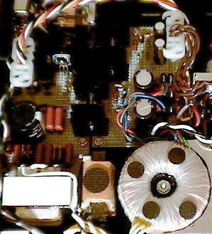
I chose to use the Hammond 1U 19″ rack-mount chassis, model RMCV190113BK1 (17x13x1.75). It was this decision, by far, that made the design of this project far more complicated than it would have been otherwise. I had to carefully observe the height of every component I purchased for it. The biggest problem in that regard was the transformers. I didn’t want to have to resort to a “floor wart” setup, but trying to find high power transformers that are less than 1-1/2 inches high is very difficult. For the filament supply, I found a toroidal transformer from Amevco that did the job nicely. For the plate supply, I initially used the same transformer as the +/-20V mux supply (36VCT, 0.35A), connecting it to the mux transfer’s secondary backwards and configuring the primary for 230VAC. The drop across the two transformers under load was far to great, so I switched to a 120VCT connected to the mains backwards. This ended up not working either (see above).
Since the plate and filament supplies would dissipate the most heat, they were also located in the ventilated area of the chassis, next to the preamplifier. In the end, convection alone was not enough airflow to keep the supplies and preamp cool, so I ended up building cooling system using some ductwork made of bits of soldered tin. Air is moved by a miniature squirrel cage fan, which is fairly quiet. The speed is controlled by the controller board, based on the internal temperatures.
Front Panel
Still trying to figure this out….
Rear Panel
I built this in a similar fashion to the front panel of the original incarnation of this project. The artwork is printed on strips cut from 11×17 sheets of photographic ink jet paper. Trying to convince my printer to print on such a long sheet was difficult, as the maximum page length is about 14 inches and it had trouble feeding such a narrow strip (HP 952c). I managed to get it to work by putting it in fan-fold banner printing mode. Unfortunately this disabled all the other print quality settings, but it came out looking decent. I then cut the artwork out and ran it through a laminator. I left about 1/2″ of clear laminate bordering the artwork, so that it could wrap around the rather curvy panel. The panel and artwork were sprayed with 3M Super 77 spray adhesive and mounted to the panel. The holes were cut out with a sharp exacto blade.
It turned out looking “OK”, but I wouldn’t want to do this for the front panel. Part of the problem is how the artwork has to wrap around the back of the curved plate in order to stay put. It seems to be staying together, but once it gets hot it will probably fall apart. Oh well; hopefully I will come up with something better. Since it is on the back of the chassis, it’s not a big priority for me.