Dad’s Williamson Amp – History
♦ Back ♦ History ♦ Description ♦ Schematics ♦ Performance ♦ Pictures ♦
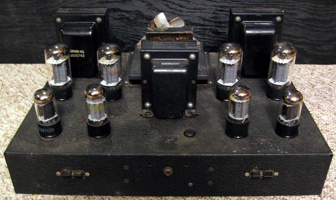
This amplifier was given to me by my father, which he built as a teenager. Some time after my parents got married, the amp was replaced with a solid state version and it spent the next 30 years or so in the garage. Somehow, even though we moved a couple of times, it never got thrown away. I guess it was my recent electron tube projects that prompted him to pass it on to me.
Overall, the amp was in pretty good shape. The tubes all have silver getters and the chassis only had some minor rust on it. There was no power transformer for the output tube plates (the plate supply was external), but the rest was all there. A separate transformer supplied the input and driver tube plate current, output tube screen current, and the heaters. The heater winding must not have had enough capacity, as an additional 6.3V transformer was connected in parallel with it. Even this must have been marginal, as the paper around the outside of the additional transformer was badly burnt even though it had a fan blowing on it.
The amp lived under my workbench for about 7 or 8 years. On occasion I had looked around for a transformer that could be used for the plate supply, but no one transformer could handle the task and they were all pricey. Eventually I got turned on to Antek, which resells chinese-made, inexpensive toroidal transformers. Some of the models are usable in conventional power supply topologies for tube circuits. Eventually I picked up their AN-4T360 model, which had enough capacity to power all of the plates and filaments in the amp. I went for a lower B+ because I wanted to be able to use other tube types. Most of the modern power tube production cannot handle plate voltages over 450V, so I settled for a safer 400-425V.
After a few years of it living under a workbench in my shop, I finally pulled it out with the intention of doing something with it. The chassis seemed large enough to fit the new transformer with enough space left for some sort of regulator for the screens. The chassis was mostly stripped down (with only the preamp section remaining), cleaned up, and repainted. I used a speckle-finish paint meant for outdoor furniture. It’s not only durable, but the rough texture hides all of the chassis imperfections. The chassis also had a lot of extra holes that I wouldn’t be using, so I found some edgewise meters and rocker switches that could be used to fill holes in the front. The huge hole in the top was covered by a large heat sink made out of glued-together aluminum U-channel stock. This is used to dissipate heat from the screen regulators and whatever else I may add down the road.
The top plate cover that held the fan and extra filament supply was reenlisted as a housing for the new solid-state power supply. The HEXFRED diodes and capacitor clamps are housed underneath with the caps poking through. A small 200VCT transformer also sits on top for the +/- 100V, 100mA supply that is currently only used for the output tube bias. I kept the old Cinch-Jones connector that was previously used as the umbilical connector for the external plate supply. This will be used as a power take-off point for other experiments down the road.