Thomas – Description
♦ Back ♦ History ♦ Description ♦ Schematics ♦ Performance ♦ Pictures ♦
Design
This amplifier is a text book implementation of a basic beam tetrode push-pull amplifier with lots of global negative feedback. The implementation and layout was probably rather typical low-fi point-to-point construction of the era. From what I can tell, this amp was actually built in 1974 1959. There was no attempt to shield input level signals or reduce hum induced into the signal (AC heaters and no twisted pairing of supply lines, etc). There was an additional section of circuitry on the amp chassis that actually had nothing to do with the amp. It appeared to be some kind of vibrato driver for the preamp (this is from an organ, remember), which had severely broken bias circuitry and was quickly removed.
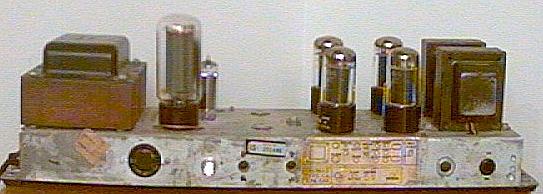
The picture below shows the amp in use with the original tubes (except for the new 5U4GB). It’s a little distorted, as this picture was taken with my webcam before I got the close-up lens. I also added a pushbutton switch, reinstalled the fuse holder, and properly grounded the chassis so the I could use the amp with some degree of safety. The large round connector was for an umbilical cable leading to an external leslie unit.
All tubes were branded “Thomas” except for the rectifier (GE), so it took a bit of guessing to figure out who really made what. I wanted to try to retube it the same way, mainly for nostalgic purposes. After unsuccessfully combing the Internet for information about Thomas Organs, I ended up looking at pictures of tubes of various makes in an effort to find similarities in the construction (plate and envelope shape, etc). I am quite certain, based on their construction and properties, that the output tubes were made by Sylvania. I then picked up a matched set of NOS Philips/Sylvania JAN 6V6GTs (clear glass) from Triode Electronics. They’re not exactly the same as the originals, but they are very close plus the originals were not JAN. The small signal tubes (12AU7 and 12AX7) are a bit of a mystery. They have gray plates and were made in Japan. If you have any guesses let me know.
Power Supply
The power supply is fairly typical except that it was designed to power about 12 other off-board tubes (12AU7s and 12AX7s). This is why the mains transformer is so huge; I’m not worried about not having enough heater or HT capacity with this beast. Rectification is provided by a GE 5U4GB, of which I was able to find an NOS replacement at KOS NOS Tubes. Also, it looks like Electro-Harmonix will be coming out with a new 5U4GB this spring (2002). Output of the B+ HT supply is about 315VDC, with a slightly lower voltage provided for the tetrode screens and another for biasing the input and driver stages. The chain of voltage dividers is pulled down by a OA2 gas reference tube, which provided a regulated 155VDC to the vibrato and oscillator circuitry. It’s not used by the power amp, but I kept the tube so that the rest of the power supply legs did not change in voltage. Besides, it has that cool purple glow. 😉
Input Stage
The input stage is 1/2 of a 12AX7 (per channel), self biased at about -1V for 0.7mA of plate current. The plate voltage is about 70V, which is directly coupled to the driver stage. Needless to say, this tube is biased quite cold, which explains why the originals seem to be in such good shape.
Driver Stage
The driver stage is a simple split load phase inverter (or “concertina”) using 1/2 of a 12AU7 and a pair of 100k resistors per channel. Since the grid is biased at about 70V, the plate current is again rather low; about 0.5mA. It is directly coupled from the input stage and capacitively coupled to the output stage via a pair of 0.047uF foil capacitors of unknown composition.
Output Stage
The output stage was a pair of 6V6GTs with a fixed bias of about -27.5V. The bias was not adjustable and was coupled to each grid via a 220k grid leak resistor. The resulting cut-off frequency of the 0.047uF coupling capacitors and grid leak resistors was about 15Hz. The plate voltage ended up being about 306V after the transformer drop, which put the static plate current at an average of about 15mA for the original “Thomas” branded tubes. A set of NOS Mazda 6V6GTs produced about 23mA and 27mA (respective to each pair) at the same grid voltage. The NOS Sylvania tubes operated at about 34mA (causing plate glow), which forced me to modify the bias circuit to achieve a lower voltage.
The output transformers are presumably of low quality, most likely with poor low end frequency response. I have yet to try to measure the frequency response of the amp, but I don’t feel like it’s missing any bass punch. In fact, it sounds more powerful on the bottom end than my transistor amp. I do know that my speakers (fairly low-cost Realistics) tend to be a little boomy at the bottom end and probably don’t go too far beyond 50Hz anyway. Speakers are definitely on my list of things to improve.
Original Configuration
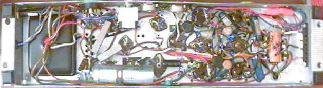
Here you can see the amp in its almost original form. The vibrato circuitry and external leslie umbilical wiring has been removed and the output bias circuitry has been tweaked to give me an adjustable voltage down to about -28.5V. There is still no means to adjust the bias for each tube.
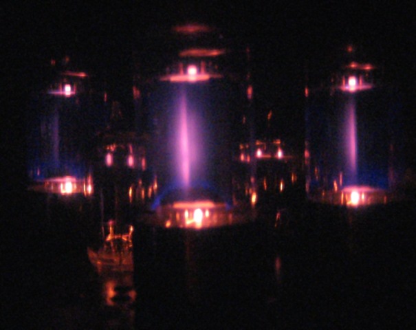 Night shot with the original tubes. Note the blue glow in the output tubes. I have read contradictory discussions about blue glow against the glass envelope. Blue glow coming from inside or near the anode or other structures is normal, but some say that blue glow outside of that means a soft vacuum. Sylvania claims the opposite and that fluorescent glow inside the envelope is normal for some tubes. It results from stray electrons bombarding near the glass envelope and will change in brightness depending on the intensity of the signal passing through the tube. This is exactly what I see with these Philips JAN tubes, which are basically Sylvania. In fact when I push the amp really hard well into cut-off, the tubes will flash brightly signaling me to back-off.
Modifications
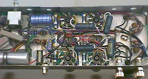
As mentioned above, the first mod was to yank the components for the vibrato circuit. The bias on the 6BA4 tube was out of whack due to a broken solder joint. The result was a fried plate and about 5x the voltage across the 25uF electrolytic capacitor section (over 150V on a 25V cap). That section of the cap was destroyed, but the rest survived. Also, most of the carbon composition resistors under the amp were well “cooked” and way out of spec. Much of the amp’s hum was due to the hap-hazard grounding, which grabbed ground from the chassis in various, random places. Eventually, I ripped all the circuitry from under the amp and rebuilt everything from scratch using the same design. All wiring was replaced with 20awg solid tinned-copper wire (insulation rated 600V) and all resistors were replaced with Holco or Vishay-Dale metal film resistors.
Power Supply
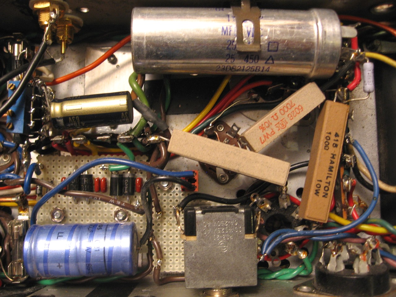
Electrically, the power supply remains largely unchanged. I replaced the two multi-section 20/20/25uF @ 400/400/25V caps with new AeroM 25/25uF @ 450/450Vcaps (25uF @ 25V sections were not being used by the amp). The electrolytic cap that was mounted to the top of the chassis was also soldered to it, so this determined my chassis grounding point. I tried to achieve some sort of star-grounding technique, it ended up less than what I hoped for. Still, the hum is reduced to almost nothing; though I know I can do better. A ground bus bar was achieved with a 14awg solid copper wire running just inside each pair of output tubes.
A DC heater supply was built for the input and driver tubes to help reduce hum. The 6.3VAC heater supply was used for this, which does not produce enough additional DC voltage to properly regulate (even with Schottky diodes). Thus, a large filter cap was required to ripple to acceptable levels and a single 1N4001 diode was used to drop the DC voltage to the correct level. The output tubes still use AC for their heaters, as their current requirements would have made an unregulated DC heater supply with sufficiently low ripple too difficult to implement.
A relay was also installed which switches a 1ohm resistor into the heater supply, while also switching off the 5V heater of the 5U5GB rectifier tube. This turns off the HT supply and the resistor reduces the heater voltage to about 4.5V, effectively putting the amp on standby. This relay will be controlled by the preamp I am building.
All AC-carrying wires were twisted into pairs the pushed into the corners of the chassis as much as possible. Each channel sports its own DC-carrying wires, routed up either side of the small tube sockets as close to the chassis as possible.
Bias Circuit
After I picked up the NOS Philips/Sylvania JAN 6V6GTs, I was forced to eek a little more voltage from the bias circuit. I replaced the copper oxide/copper diode with a Schottky silicon diode (11DQ04). Schottky diodes are fast switching, soft recovery diodes, which reduces the EMI induced in the power transformer by power switching. They also have a lower forward diode drop (0.55V) than a typical silicon rectifier, which in total gave me another -2 volts or so in the bias circuit. Each output tube has its own 10k cermet multi-turn trim pot to adjust the bias voltage to improve anode current matching. This was required over the bias+balance pot method, since I needed to get as much voltage from the bias supply as possible. The output of each pot is bypassed by a 10uF capacitor at each tube to prevent signal crosstalk.
Audio Stages
The chassis was fitted with gold plated RCA jacks for the input and banana jacks/binding posts for the speaker outputs. Both are insulated from the chassis. Shielded audio cable was used between the RCA jacks and the input tube grids with signal ground termination occurring on the bus bar near the grounding point for the grid leak resistors. Shielded cable was also used between the output of the global feedback network (located at the speaker jacks) and the input tube cathodes.
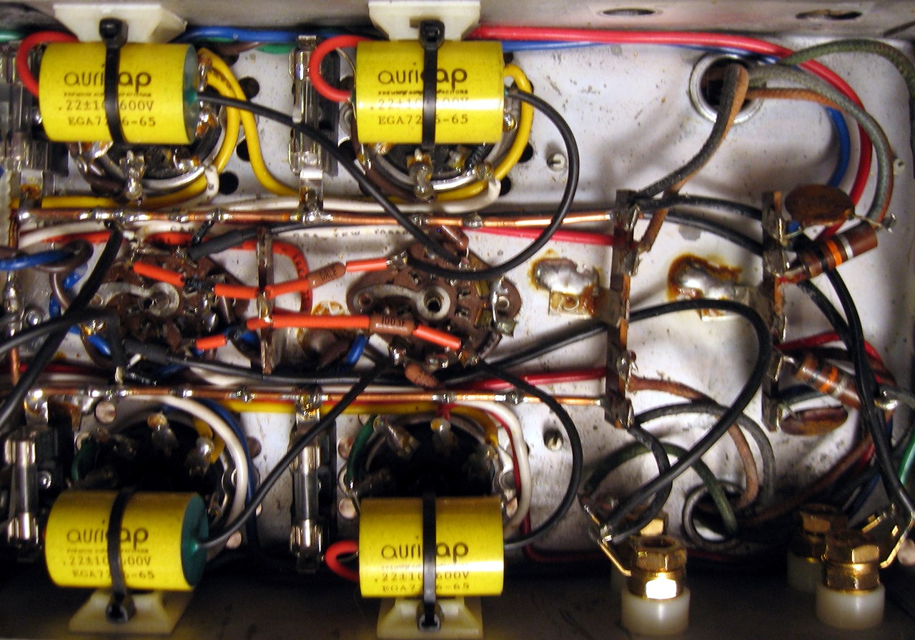
As mentioned above, all resistors were replaced with Holco or Vishay-Dale resistors. Since the current production Holco resistors are NOT made with non-ferrous end caps, Vishay-Dale resistors were used where old production Holcos could not be obtained. The driver-output coupling caps are 0.22uF Auricaps, well respected for their transparency and reasonable cost. This reduced the cut-off frequency to 3.3Hz. I did notice a slight improvement in bass response, but the limiting factor is probably still the output transformers. I have no plans to replace these.
Even with -29.5V at the grid (about 28mA plate current), the new Sylvanias still have glowing lines on the plates from the electron beam. I have read that this may be OK for some tubes, but it still bothers me. The measured transconductance (printed on the tube boxes) is a little high for a 6V6GT, which probably explains why they are so hot. The cathodes were fitted with fuses that are connected to the ground bus bar. They are not there to protect the driver tubes, as fuses have non-linear resistive properties. Also, since output tubes are driven so close to their maximum dissipation limits and fuses need to be overloaded by 200% or more to blow quickly, the tubes would be destroyed long before a properly rated fuse would blow. Instead, a large 3A fuse is installed which permits convenient cathode current measurement (by removing the fuse and connecting an ammeter), as well as a mounting point for the ground bus bar.