Tubelab Simple SE – Construction
♦ Back ♦ Description ♦ Construction ♦ Performance ♦ Pictures ♦
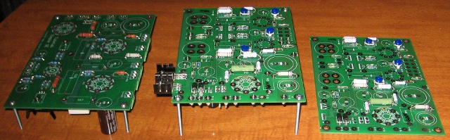
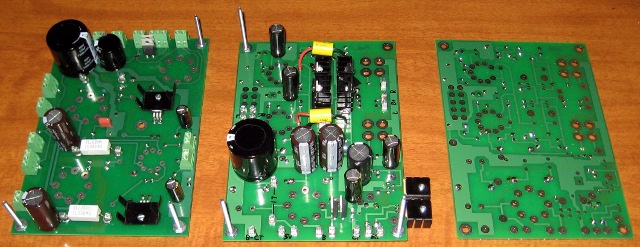
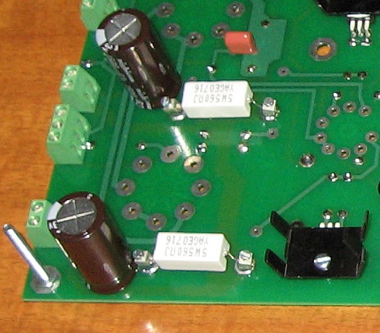
I already had a lot of the parts needed to build this amp. I ordered a pair of Tubelab SE boards along with this one. Once the PCBs were on hand, the boards were stuffed and soldered in a few hours. Both were built for flush chassis mounting, which means the tall items are on the bottom. The sockets are also absent, since it is better to solder them in once the chassis holes are cut. The instructions are very detailed and cover just about every scenario, as they are aimed at the beginner. They do have you soldering the sockets early on, but this is only important if you are building the PCB with all the components on top.
The Simple SE design is very versatile in terms of what output tubes can be used. Pretty much anything that is pin-compatible with the EL34/6L6/KT88 family of tubes will work, as long as they can handle whatever B+ voltage you choose to run. I chose 450V, which is as high as I can safely go with the 500V capacitors. To get the most out of a tube type, it is helpful to tune the cathode resistors to the tubes in use. This way the tube is running at a plate current that results in the best sound for that tube. I used the same binding posts that I used on my Tubelab SE in the cathode resistor position to make resistor swapping easier.
The power and output transformers are from Edcor. This is the first time I have used them and I have to say that I am impressed. They are very reasonably priced, better than most Hammond iron, and they work as specified. Hammond’s power transformer quality is getting worse as the years go by. They seem to be using less copper in their primaries, which makes them run very hot (even with no load) and also makes them buzz and leak flux like crazy due to core saturation. The Edcor models I am using are:
XPWR035 - 370-0-370 @ 200mA, 6.3 VCT @ 5A, 5V @ 2A

CXSE25-8-5K - Primary: 5000kΩ, Secondary: 8Ω, 25W
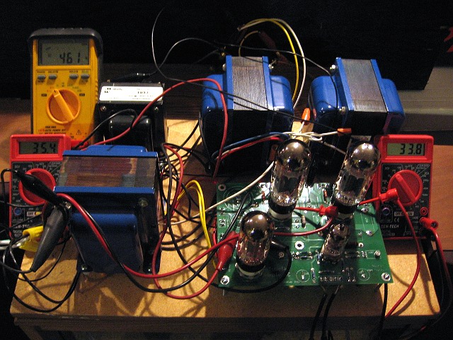
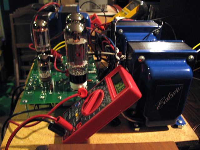
On the breadboard, the power transformer barely got warm after several hours of use. The amp sounded great. My only grip with the output transformers is that the secondaries are not tapped for 4 ohm speakers. This is a minor issue though, since all of my speakers right now are 8 ohm. Here is the amp on the breadboard with JJ 6L6GCs installed:
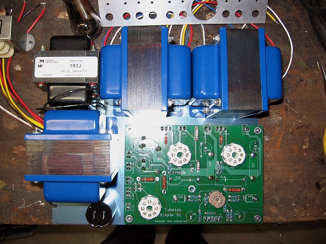
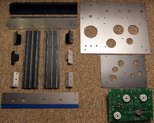
Next up was the chassis. I originally was going to put it all on a 12×10 chassis that I had, but I quickly realized that that wasn’t going to work. It’s just too crowded:
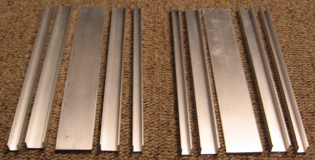
George Anderson from Tubelab built one of these in a style inspired by Morgan Jones’ “Bevois Valley” amplifier from the book “Valve Amplifiers”. I also liked how Jones’ chassis looked, which gave me the idea if building something that is a cross between that and a car stereo amp. Sort of a large, finned extrusion with glass and iron bolted to the top. I had a bunch of aluminum U channel stock that I glued together to give the sides that finned look:
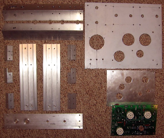
I also had some 2″ right-angle stock from another project and found a 1/8″ plate at an industrial surplus store. I like the clean look that you get with the tubes recessed into over sized holes so that you can’t see the sockets. However, to fit the rather large-based 6550/KT88s, these holes had to be fairly large. To keep small objects and curious fingers away from the PCB, I added a thin plate that flush-mounts to the sockets. After a lot of cutting, milling, gluing, and drilling and drilling and drilling, I had all the pieces that I needed:
It was then time for a test fitting of all the components:
The only issue that I had with the fitting was that the fuse holder comes very close to the choke. Other than that, it all fit great.
Next up was the paint. Everything was sanded and primed in flat black and the plan was to make the chassis all satin black. Well after seeing it all in primer, I decided that look was a bit too dull. So the top plate and front panel are painted with some “hammered finish” black/silver paint. I’d say it is mostly silver, but it looks better than all-black plus the hammered look hides any surface imperfections and future dings and scratches. I then masked-off the insides of the side panels and gave the ends and edges the same hammered treatment. It makes for a nice contrast. I also put a blue highlight on the front panel to mirror the Edcors. Here is everything after being painted:
Assembly took longer than anticipated. I made a few design changes along the way that required some drilling on the chassis parts after they had already been painted. One was the installation of a cathode bias resistor selection switch:
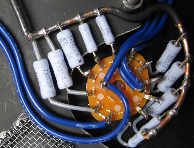
One of six resistors in put in parallel with a 680 ohm resistor. They are 680, 750, 910, 1.2k, 1.5k, and 3.3k. This allows the tube current to be experimented with and optimized for a particular tube type. I came up with these values using a spreadsheet that I made that takes George’s simulated values to see the results of different scenarios. You can download it here.
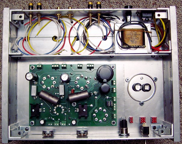
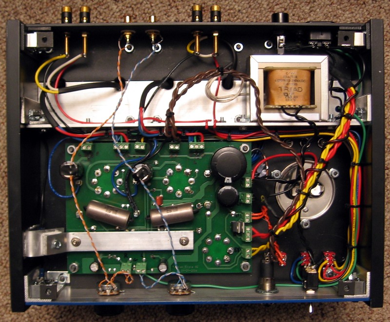
The wiring also took a great deal more time than expected. The flexibility of the Simple SE PCB allows for a number of configuration choices: tube or solid-state rectifier, triode or ultralinear, and cathode feedback. I decided I want to make all of these selectable. Thus there are a lot of wires from the back of the PCB to the front of the chassis where the switches are.
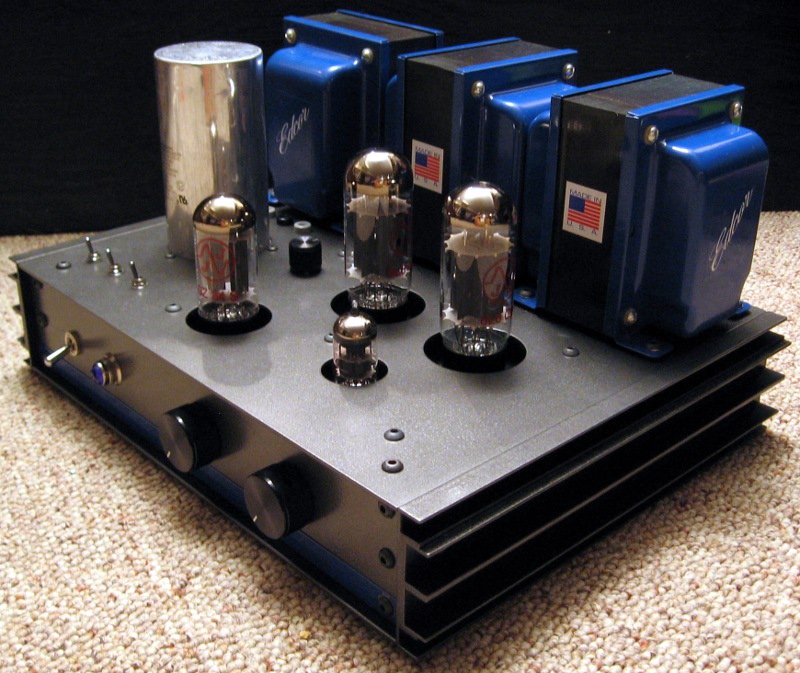
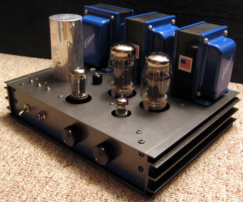
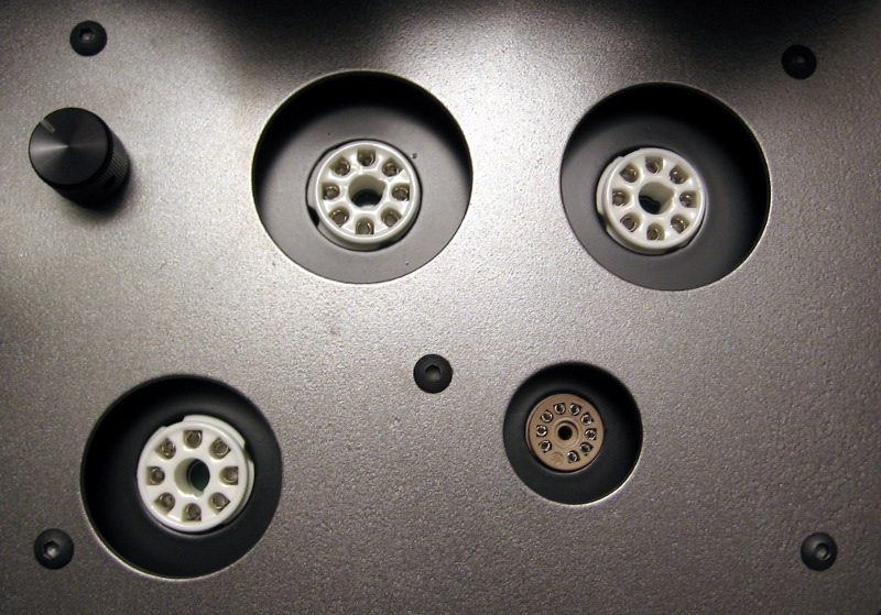
The recessed sockets turned out well and gives the amp a cleaner look. You can see the bias select knob on the left.
Behind the film/oil cap are three banana jacks that can be used to measure the voltage across the cathode resistors. This way the cathode current can be observed for various resistor values. It seems kind of funny to have to check the bias on a cathode-bias amp, but it’s all in the name of science:
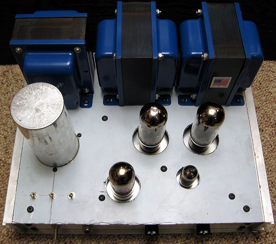
The finished amp looks good with both narrow tubes, like 6L6GCs and fat tubes, like the KT88s: